'Gloworm Mk1' Mine exploring headtorch
This page is all about my home-made mine exploring headtorch. It is called the Gloworm as a kind of ironic reference to it's brightness.
It looks like this. Note that the power pack needs a bit of rework to make it smaller and watertight!
It is an 11300lm battery powered LED headtorch.
The spec is as follows:
- 12x Cree-XM-L LEDs
- Max current per LED = 3Amps = 943lm
- Thermal cutoff at 70degC
- 4x LEDIL Cute3-SS-XM optics (+/-9.5degree beam)
- 3000mAh 18.5V Li-Po battery, 35C discharge
- 4 independent channels, using LT3690 switching step down converter
- STM32 CPU (32bit ARM Cortex-M running at 72MHz)
- USB virtual com-port for diagnostics
- Lamp assembly sealed to IP67 (hopefully!!)
- Backup LED automatically illuminates under fault / powerdown conditions
- 8 hours runtime on lowest setting (400lm)
There are 7 brightness settings:
- 400lm (3 LEDs)
- 1600lm (3 LEDs)
- 2800lm (3 LEDs)
- 1600lm (12 LEDs)
- 6400lm (12 LEDs)
- 11300lm (12 LEDs) - for 5 seconds only before dropping to 6400lm
Why?
Well, the world is moving LED, and getting brighter. My old FX-Headlite was becoming eclipsed by the Scurions and Stenlights. The biggest two issues were the continual dazzling by others, and the fact my night vision never really reached it's full potential because of the high levels of light. So when I found myself alone, I couldn't see much!
Therefore I decided to make a new light, and set the target of exceeding 10000 lumens. The idea being that it's so far ahead of anything else (as of 2012), that it will be a decade or so before I need to think about upgrading.
Design
Conventional LED drivers are PWM drivers. By this I mean they switch the LED on and off very rapidly to give the impression of variable brightness. Watch the rear end of a modern car go past you through the corner of your eye and you'll notice the red lamp flashes. With this approach, if you wanted a max LED current of 3Amps, your driver would pulse the LED with 3A pulses right up to a continuous current for full brightness.
I decided that what I wanted was an analogue constant current supply that could be controlled up to 3A. But when a lower brightness was desired, the current would be reduced, rather than pulsing the LED at 3A.
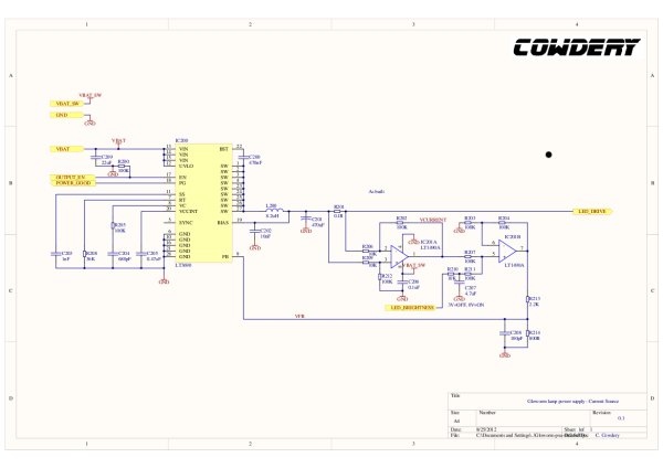
No IC's seemed to be available, so I took a voltage supply IC and added some of my own circuitry. In short, I take a current measurement from the output (via a 0.1ohm resistor), convert to a voltage, scale it, add in the brightness setting, and feed it back to the voltage supply IC.
Like this (clicky for full-size):
 |
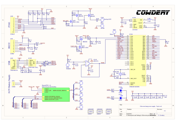
Four channels of that, supervised by a microcontroller with some ancillary stuff, like a remote temperature sensing circuit and a high efficiency supply for the microcontroller. Also a backup LED circuit, designed to come on if the microcontroller is in reset, and a battery voltage monitoring circuit so the torch can alert the user that the battery is becoming exhausted.
 |
Lamp assembly mechanics
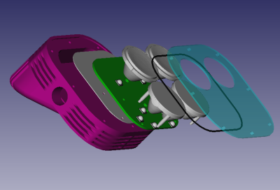
The lamp housing is machined from a billet of aluminium to my design. I knocked up a 3D cad model in a free program called FreeCAD. It's not bad for a free program, although I think I pushed it to it's limits with this design!
The CAD model looked like this:
 |
Notice that I designed it for either 1 or 3 LEDs in each of the four clusters, the 3D cad has single LEDs in the upper two clusters. I didn't build it this way in the end, I went for 3 LEDs in each cluster.
So I sent out the STP file to get that part made.
I initially made the PCB for the LEDs from FR4 (i.e. conventional green PCB material), but quickly realised that even with 3 solid copper fills and 500 via holes, the thermal characteristics just weren't up to it.
A fortuitous tour of a PCB assembly facility alerted me to the possibilities of IMS - Insulated Metal Substrate. IMS is basically a piece of aluminium with a wafer thin layer of FR4 on top, specifically designed for power applications.
So I had the lamp PCB remade on IMS by EuroCircuits, to give me the best chance of taking the heat away from the LEDs (which is considerable at full power)
A minor point here is that because the IMS is so darn good at heat dissipation, it's not possible to solder the LEDs on without the proper equipment. So I had to fork out to have a solder stencil made, and the board assembled professionally. I used First SMT in Letchworth. Worth it though as it looks the part (and works very well!)
The power supply PCB is pretty conventional, just squeezed down by using 0402 components and surface mount throughout. I assembled it with a microscope and a hot-air gun, all DIY propositions as long as you have a steady hand.
So the final assembly looks like this:
Schematics and PCBs were designed using Altium Designer, and the microcontroller programmed using IAR Embedded Workbench. Altium needs a subscription, which I had at work, but IAR has a free version for small projects, which this is.
So, how well does it work?
First pictures are outside at night
An FX Headlite as a baseline reference:
400lm from 3 LEDs:
2800lm from 3 LEDs:
1600lm from 12 LEDs:
11300lm from 12 LEDs:
And at a different location
400lm from 3 LEDs:
2800lm from 3 LEDs:
1600lm from 12 LEDs:
11300lm from 12 LEDs:
Car headlights on main beam:
